Singularity Free Design
Wide Angle Gimbal
 Highlights
- Full hemisphere singularity free pointing range
- Agile dynamic response
- Platform stabilization and target tracking applications
- Extensive development support framework
Background and Challenges
A successful mobile laser communications solution facilitates means to acquire and maintain a communications link between two platforms subjected to a wide range of relative and rapidly changing positions and orientations. A full 180º hemisphere of operating range offers sufficient coverage in the vast majority of situations and is considered a minimum requirement for practical deployment.
In addition to the actual operating range, it is important to consider how the range is covered, especially in terms of continuous motion. In critical applications, it is not acceptable to interrupt the communications link in order to reposition the transceiver when the pointing mechanism reaches the end of its continuous range or approaches a region affected by singularity. This problem can sometimes be addressed by adding a third axis and using rotary electrical and optical joints that enable continuous operation. It is desirable from a systems integration standpoint to achieve the wide-range singularity-free pointing task without sacrificing continuous mode of operation or compromising the integrity of the electrical and optical signals.
Conventional Gimbals
Traditional electro-optical system pointing mechanisms based on cascaded arrangement in alt-az / az-el / yaw-pitch configurations trade off simple construction and straight forward (albeit nonlinear) control for reduced motion range limited by kinematic constraints. Additionally, the mass of the second stage actuator negatively impacts the dynamic response along the axis of the first stage actuator.
New Generation of Gimbals
The innovative kinematic structure of the pointing device developed in this project offers singularity-free access to the 180º hemispherical range. A transition between any two points in the operating range can be achieved along a direct and uniformly smooth trajectory without cable winding and without the use of slip rings or similar technologies. In fact, no special precautions beyond minimum cable flexure are necessary for continuous operation. The design leverages the attachment of both actuators to the stationary base, which enables very fast acceleration of the moving platform.
Description
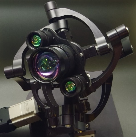
 The parallel robotic linkage consists of four arms comprised of three links each that connect the stationary base to the moving platform using a total of sixteen revolute joints. With two spatially offset artificial pivot points, the relative position and orientation between the stationary and the moving platform is constrained similarly to a double universal joint.
Dual rotary actuators drive two of the four links attached to the stationary platform to achieve a full 180° hemisphere of unobstructed motion.
Control System
Besides extended motion range and improved dynamic response, the novel kinematic design presents increased mechanical complexity along with static and dynamic nonlinearities. The full capabilities of the device can only be unlocked with a carefully designed control system.
Static nonlinearities and cross-coupling are eliminated in a fully decoupling controller based the solution of the kinematic equations governing the motion of the mechanism. With static and dynamic decoupling, the controller achieves excellent operation at slow speeds throughout the whole motion range. At high speeds, performance variation associated with different dynamic behavior at different operating points requires additional model refinement. Efficient tracking depends on globally uniform behavior that was attained by constructing a map of responses and corresponding control system parameters and developing a gain switching controller that continuously adjusts its parameters based on the operating point.
The following figure demonstrates the variation in the dynamics throughout the operating range (left) and the mitigation of this variation by the gain switching controller (right).


User Interface for Design and Analysis
A custom graphic user interface was employed in efficient collection and analysis of the dynamic response of the system and validation of the performance of the normalizing controller.

The normalized system then served as the foundation for a closed-loop tracking controller. This arrangement is advantageous since the quadrant detector that was used as a primary feedback device, was mounted to the moving platform, exposing the controller to all of the underlying dynamics. The quality of the output of the sensor required additional processing which was implemented by applying an interpolated grid of calibration data and validated with the help of dedicated user interface.

The closed-loop reference model design was optimized for peak tracking performance using the collected response data and a custom visualization console.
Analysis and visualization of the overall tracking performance was realized on another user interface panel.

The high-level operation of the entire system is controlled through a screen that provides access to various functions and status overview.

Videos
Conventional Azimuth / Elevation Gimbal
Newtonian telescope optical tube assembly mounted on an azimuth / elevation platform with limited dynamics and pointing range.
High Speed Gimbal
Low inertia high-speed parallel robotic manipulator demonstrating a full-hemisphere range of singularity free motion. The mechanism enables transitions between any two points within the operating range along a straight line without gimbal lock.
Platform Stabilization
Extended Kalman filter inertial measurement unit fusing data from three solid-state sensors provides orientation feedback in this platform stabilization implementation. A high-frame-rate video camera was used to capture slow motion sequences for closer analysis.
Closed Loop Optical Tracking System
The target is designated by a red laser and followed by the motion platform that projects a green laser spot to indicate its orientation. A small offset is introduced for clarity.
Small Form Factor Gimbal
An alternative gimbal configuration with a smaller ø50mm moving platform but defined by the same kinematic constraints demonstrates high motion agility and stabilization performance. Inertial measurement unit fusing data from MEMs sensors provides reference orientation signal.
Motion Range CAD Simulation
Full hemisphere motion range kinematics. Two degrees of freedom.
Specifications
| Azimuth Range | 360° (continuous) |
| Elevation Range | 0° – 90° |
| Maximum Speed | 1600°/sec |
| Control Interface | RS-232 |
| Size | 432mm x 280mm x 260 mm |